
How to Fix Broken Solar Pathway Light Wiring: Electrical Diagnostics and Micro-Soldering Guide
Imagine your solar path light stays pitch dark at night, even though the solar panel sits in direct sunlight all day and the rechargeable battery tests at full voltage on a meter. When clean panels and healthy batteries fail to produce light, internal wire breakage, corroded solder joints, or rotted ON/OFF switch contacts are almost always the cause.
To repair solar pathway light wiring, disassemble the housing and test low-voltage DC continuity using a multimeter across the solar panel, battery terminals, switch pads, and LED circuit board. Resolder broken lead wires using flexible 28-30 AWG stranded wire, a 15-25W micro-soldering iron, and adhesive-lined waterproof heat-shrink tubing to permanently restore continuity and maintain an IP65 weatherproof seal.
Multimeter Diagnostic Flowchart: Pinpointing Internal Electrical Breaks
- Step 1: Is battery terminal voltage above 1.2V DC (NiMH) or 3.2V DC (LiFePO4 / Li-ion)? → Yes: Proceed to Step 2: Test Mechanical Switch Continuity.. No: Recharge or replace battery before testing wiring traces..
- Step 2: Does the mechanical switch show 0 Ohms continuity when set to the ON position? → Yes: Proceed to Step 3: Test Solar Panel Open-Circuit Voltage.. No: Switch contacts are corroded. Bypass switch by bridging SW1 and SW2 pads on PCB..
- Step 3: Under ambient light, does the PV panel read >1.5V (1.2V system) or >4.0V (3.7V system) across PV+ and PV-? → Yes: Proceed to Step 4: Test LED Lead Continuity and Diode Drop.. No: Broken panel lead wire or cracked PV substrate. Resolder panel wire leads..
- Step 4: Does the LED illuminate briefly during multimeter Diode Test across LED+ and LED- pads? → Yes: Wiring and LED are functional; main control IC on PCB is damaged. Replace PCB.. No: Broken wire lead between PCB and LED, or cold solder joint on LED leg. Resolder lead wire..
Voltage & Continuity Fault Matrix (Side-by-Side Comparison)
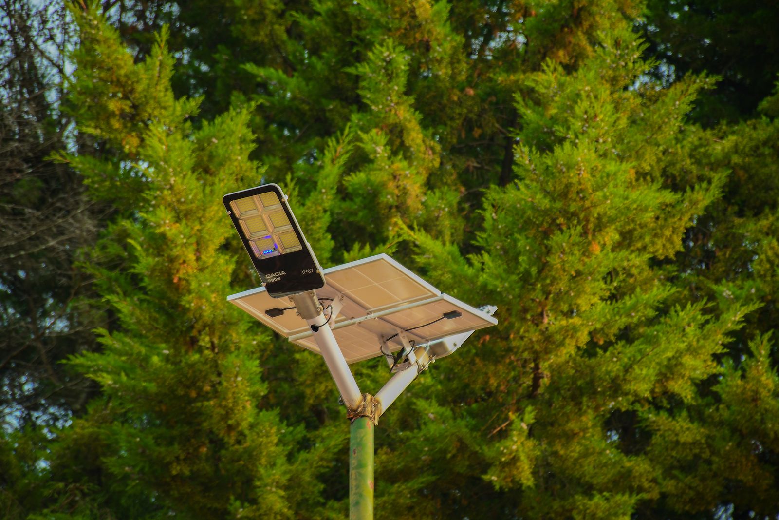
Photo by finix photographer on Pexels
| Real-World Scenario / Symptom | Multimeter Test Point & Setting | Normal Expected Value | Diagnostic Result & Electrical Fix |
| --- | --- | --- | --- |
| Light flickers when pole is bumped or gently tapped | Continuity test across wire bend points and solder pads while flexing wire | Constant continuous beep (0 Ohms) | Intermittent wire fatigue or cracked solder joint. Strip wire end back to fresh copper and resolder joint. |
| Light remains dark; battery is known to be fully charged | Continuity across SW1 and SW2 terminals with switch ON | Beep / <0.5 Ohms resistance | Internal switch leaf contacts rusted. Cut switch wires and solder bridge directly across SW1 and SW2 on PCB. |
| Light turns on briefly when panel is covered, then dies instantly | DC Voltage across BATT+ and BATT- under LED load | >1.20V DC (NiMH) or >3.60V DC (Li-ion) | High-resistance corroded joint on negative battery lead causing drop under load. Cut back oxidized black copper and resolder with rosin flux. |
| Battery never charges despite bright daylight exposure | DC Voltage across PV+ and PV- terminals in daylight | 1.8V - 2.2V DC (NiMH) or 5.0V - 6.0V DC (Li-ion) | Broken solar panel wire lead or corroded PV blocking diode. Resolder panel leads with fresh 28 AWG wire. |
| LED stays dimly lit during daylight hours | DC Voltage across PV logic pad (L/S pin on control IC) | Equals panel open-circuit voltage in light (>1.5V) | Delaminated solar panel or shorted circuit trace allowing logic voltage to float. Clean PCB trace with 99% isopropyl alcohol. |
Compare real-world fixture behavior against expected electrical test values to diagnose mechanical switch failure, wire fatigue, or board joint oxidation.
Pro Tip: Micro-Soldering 30 AWG Wires Without Melting Plastic Housings
Outdoor solar path lights use ultra-thin 28 AWG to 30 AWG stranded copper wire welded onto tiny surface-mount pads inside heat-sensitive ABS plastic housings. Using a standard 40W+ automotive or stained-glass soldering iron will instantly vaporize the tiny copper trace from the fiberglass PCB and melt the surrounding plastic casing within seconds.
Always use a low-wattage iron (15W to 25W) or set a temperature-controlled station to a maximum of 300°C (572°F). Before applying heat, clip a small steel hemostat, miniature alligator clip, or copper locking tweezers onto the wire lead directly between the solder joint and the plastic housing pass-through. This metal clip acts as a thermal sink, absorbing excess heat before it can migrate down the copper strand and melt the plastic body.
Decision Tree: Repair, Switch Bypass, or Board Replacement
- Is the copper wire end dark green/black, or is the solder pad lifted from the circuit board? → Yes: Trim wire back to bright bare copper. If pad lifted, scrape green solder mask off adjacent trace to expose fresh copper before soldering.. No: Proceed to switch assessment.
- Is the slide switch internally rusted or filled with white moisture crust? → Yes: Bypass the mechanical switch completely. Desolder switch wires and solder a direct jumper wire between SW1 and SW2. Light will operate automatically in dusk-to-dawn mode.. No: Proceed to component integrity check.
- Does the 4-pin integrated control chip show physical burn marks, potting cracks, or shorted pins? → Yes: The controller IC is fried. Replace the entire control board with a universal 1.2V or 3.7V solar landscape light driver PCB.. No: Keep original PCB. Solder new 28 AWG stranded leads, coat in rosin flux, and heat shrink.
Immediate Diagnostic Actions & Practical Next Steps
Your decision: Determine whether your unlit solar pathway fixture requires wire trimming, an ON/OFF switch bypass, or total moisture re-sealing.
Do this next: Disassemble the housing, trim corroded wire ends back to clean bright copper, bridge rusted switch contacts on the PCB, and seal all housing pass-throughs with neutral-cure silicone.
Related resource: Pillar Guide: Troubleshooting and DIY Repair for Solar Pathway LightsMarine-Grade Dual-Wall Waterproof Heat Shrink Tubing Kit (3:1 Shrink Ratio with Adhesive Lining)
Ready to bring your solar landscape lights back to life? Grab your multimeter, clip off oxidized wire ends, and prepare your soldering iron.
Core Electrical Diagnostic Takeaways
Keep these essential low-voltage electrical repair principles in mind whenever working on outdoor solar fixtures:
Schematic: Low-Voltage Solar Light DC Circuit Layout
Understanding how low-voltage current flows between the solar panel, control IC, battery, and LED makes tracing broken wire leads straightforward.
Recommended Gear for Low-Voltage Solar Repair
Having precision micro-soldering tools and true outdoor weatherproofing supplies is critical when working on fragile 30 AWG solar wiring.
Repair Execution & Seal Curing Timeline
- Minutes 0 - 15 — Disassemble housing lens and top cap. Inspect circuit board for green copper corrosion or broken wire leads.
- Minutes 15 - 30 — Perform multimeter voltage tests on battery and panel. Test switch continuity and bridge rusted switch pads if needed.
- Minutes 30 - 45 — Strip wire leads, slip heat shrink tubing onto wires, coat exposed copper in liquid rosin flux, and micro-solder joint connections.
- Minutes 45 - 55 — Slide adhesive heat shrink over soldered joints and contract with heat gun until internal glue oozes from wire ends.
- Minutes 55 - 65 — Reassemble housing; inject neutral-cure silicone into wire grommets, seam joints, and screw hole recesses.
- Hours 12 - 24 (Cure Phase) — Allow silicone to cure fully in a warm room before reinstalling fixture outdoors in garden soil.
Pre-Repair Electrical Safety & Tool Checklist

Photo by Qeis Ismail on Pexels
- [ ] Digital multimeter with thin needle probes
- [ ] Fine-tip soldering iron (15W-30W or temperature-controlled set to 300°C / 572°F)
- [ ] 60/40 rosin-core or lead-free SAC305 solder wire (0.8mm diameter or thinner)
- [ ] 28-30 AWG flexible stranded copper wire leads (silicone insulated preferred)
- [ ] Adhesive-lined (dual-wall) waterproof heat shrink tubing (1.5mm - 3mm diameter)
- [ ] Precision wire strippers capable of stripping 30 AWG wire without severing strands
- [ ] Neutral-cure silicone sealant (non-corrosive, non-acetic) for IP65 housing re-sealing
- [ ] Isopropyl alcohol (90%+) and cotton swabs for cleaning green copper corrosion residue
- [ ] Miniature hemostat or locking copper tweezers to serve as a thermal heat sink
Step-by-Step Procedure: Diagnostics, Micro-Soldering, and Weatherproofing
Follow this step-by-step physical repair workflow to safely strip, solder, bypass, and weather-seal broken solar fixture wiring.
Common Wire Splicing and Waterproofing Blunders
Avoid these frequent electrical mistakes that cause low-voltage solar repairs to fail shortly after installation:
Frequently Asked Questions
Direct expert answers to technical wiring, switch bypass, and waterproofing challenges.
Related Troubleshooting and Maintenance Guides
- Troubleshooting Solar Light Terminal Corrosion: Repair and Weatherproofing FAQ
Final Summary & Troubleshooting Checklist
Your decision: Verify that all open solder joints are covered with adhesive heat shrink and housing grommets are sealed with neutral-cure silicone.
Do this next: Perform a final bench test by placing the battery inside, covering the solar panel with dark cardboard, and confirming immediate bright LED illumination.
Related resource: Pillar Guide: Troubleshooting and DIY Repair for Solar Pathway LightsMarine-Grade Dual-Wall Waterproof Heat Shrink Tubing Kit (3:1 Shrink Ratio with Adhesive Lining)
Before putting your soldering iron away, double check your electrical work to ensure long-lasting outdoor performance.
Cover photo by Ajay at TWL on Pexels.